This link will take you to it: PanelPilotACE University.
The RS232 works using three elements: one hardware element (Serial COM Port) and two function elements (RS-232 Receive and RS-232 Send).
Within the hardware element you must specify standard RS232 properties (baud rate etc.). You must also specify the service type; native if you wish to communicate with another PPA device, Terminal otherwise. The ‘Terminal Mode’ property specifies whether the data should be wrapped with a prompt (easy to use within a terminal) or should be raw (device to device). Then you will need to specify send/receive terminators and separators.
The RS-232 Send element allows you to specify a serial port (the hardware element) and then numerous ‘Send Values’. This element can be called like any other action, and when called, it sends each value (enclosed within specified pre and post messages) separated via the ‘Send Separator’ and ended with the ‘Send Terminator’.
The RS-232 Receive element allows you to specify a serial port (the hardware element) and an alias. The alias serves as the command keyword. It can trigger actions once receive has been completed, e.g. updating text boxes or variables.
We are in the process of creating further tutorial videos to aid in development with new features.
Once you have installed the new version of the design studio you will have access to the automatic update feature. This works for both the design studio and the device software. If you have a device connected that does not have the latest version of device software then you will see a cog icon next to the device. Simply click on this and follow the steps to upgrade your device software. You can also manually upgrade your device by clicking the device menu icon (three white stripes) and selecting ‘Upgrade Device Software’.
Yes, but not directly. An interface circuit would be required to convert the PWM output to a 4-20mA output. There are third-party devices which can do this — please contact us for further help.
The Design Studio software from version 4 onwards includes a Number Spinner functional element. In previous versions, this required 8 different functional elements.
The Number Spinner function is now much easier to implement in your project.
The software is free to use and you can install it on as many PCs as you like. What you’re not allowed to do is sell the software, reverse engineer, or modify it in any way.
While the current software release does not allow you to make use of these, our software team is busy adding these features. This feature is a top priority and is expected to be available soon.
This is an issue with Windows 8 and requires you to disable driver signature enforcement. Instructions for doing so can be found in our Installing Panel Pilot Driver On Windows 8 documentation.
Open up the Panel Pilot ACE Design Studio and connect your device. Assuming your device has connected correctly, select it in the Device dropdown box in the top right of the studio. Click the menu button (three white horizontal lines) next to the device selection, choose ‘Device Configuration’, tick ‘Set Real Time Clock’, adjust the time, and click Configure to update.
The mounting bracket is located in the box below the white tray which holds the SGD 43-A in place.
Yes. The development board (SGD 43-A-DK+ — this includes a display) generates all the inputs and indicates all outputs available on the SGD 43-A. Analogue inputs can be varied using dials, digital inputs can be toggled with switches, and outputs are shown by status LEDs. Screw terminals are available for quick connection to signals.
Yes, the Panel Pilot ACE does support animated GIFs!
Certainly! Using our PanelPilot Custom Design service, we can make bespoke configurations that are tailored to your requirements. Please contact our sales team to find out more.
The rendering engines used on the emulator and on the embedded display differ slightly, which can cause very minor differences in graphic placement or rotation alignment.
The SGD 70-A already has the RS485 hardware built in and so no add-on board is required.
Currently ASCII-based raw data and MODBUS. We are working to add new protocols such as CANBUS. If you have any you’d like to see, please contact us.
PL1 selects which additional pin will be used (PWM3 or DIG8). PL2 connects or disconnects the terminating resistor from the circuit.
SGD 43-A:
Go to your project settings and enable RS485. This disables PWM1 and PWM2 for RS485 and lets you select either Digital Channel 8 or PWM Output 3 as the third pin. Match this with the jumper position on the board.
SGD 70-A:
The SGD 70-A has dedicated pins for RS485 and requires no project configuration or add-on board. Use it like RS232 (with an RS485 COM port).
CAN bus can only be used on the SGD 70-A and requires add-on board S70-CAN. CAN bus is not available on the SGD 43-A.
The J1939 protocol.
One channel.
1. Open the PanelPilotACE Design Studio software with an active internet connection.
2. Ensure the device has Ethernet hardware (built into SGD 70-A or add-on for SGD 43-A).
3. Connect via USB and open the Device Settings menu (burger icon top right).
4. Choose Device Configuration → check ‘Get MAC Address’ to request a new one.
5. The address will populate automatically from the server.
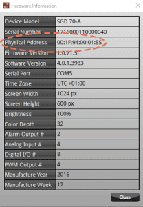
6. Click Configure to save, then verify it under Hardware Information.